Thursday, December 9, 2021

Engine Tweaks

This plane is nearly ready to go!  I'm just chasing down a few engine quirks.

I spent quite a bit of time adjusting the secondary ignition timing.  I started with the static setting which ran okay, but my RPM drop when I checked the two systems was still a little high.  I tried checking and adjusting the secondary timing with a timing light and a helper, but that didn't make much of an improvement, as didn't really seem all that safe either.  Finally I settled on just running the engine, moving the trigger cap a tiny bit, running it again, and repeating that until it stopped running better and started to run worse.  Then I moved it back to where it seemed the best.  I think that's the best I can do on the ground!

The other thing was an oil leak at the turbo outlet.  I've sealed the oil sump to the turbo at least twice, and it'll stay sealed for a while but it seems to spring a leak if I do a high power runup.  I think it's probably more of a high temperature issue than pressure related.  Sonex sent me a little adapter plate to put between the turbo and the sump, and I also bought the highest temperature sealant I could find, and so far it's been good!  Sonex also asked me to check the ports in the oil pump as some had been setup wrong, but mine was all good.  I guess that could have stopped the pump from scavenging oil correctly and cause oil pressure to increase in that return line, but I don't think that was the problem anyway.

We'll see if it leaks again!


Sunday, November 28, 2021

Fuel Level Probe Calibration (3)

3 hours

This was simple but it just took a while.  In order to calibrate the fuel level probe, I had to start with an empty tank and then add fuel in known amounts and record the sensor's output on the G3X, at both a level flight attitude and with the tail on the ground.

I just added two gallons at a time and then calibrated it in each attitude, until the tank was full!

Friday, November 26, 2021

More Cowl Adjustments (9)

9 hours

OK, now I'm really getting down to the last few things (I think).  I can not fathom any way to get the upper cowl on and off, the way the plans have it attach, with the prop installed.  So, I decided to slightly modify the aft edge of the cowl so it doesn't have to be wedged under the lip on the front of the windshield skirt.  Then hopefully it can be installed and removed vertically and stay out of the space that the prop is occupying.

Here is my inspiration.  This is an RV-8, and this picture is from the Skybolt website (which is where I got all my cowl fasteners anyway):


So, I will cut the aft 1/2" or so off of the fiberglass, remove the female Skybolt receptacles, install a bunch of those little tabs, put the receptacles on the tabs, and then the cowl will just sit on top of the tabs with the fasteners holding it down.

First, I removed the prop so I could get the cowl on.  Then I traced the front edge of the windshield skirt onto the cowl, and removed it.  Then I drilled out all of the receptacles, and then cut along my line to remove the aft edge of the cowl.


The little pins that hold the clip out on these fasteners while they're adjusted were all long gone, so I made some replacements out of safety wire.  I later found out that these fell out a little too easily, and the stems from 3/32" rivets actually worked much better.


Next I made a bunch of tabs, and drilled them for the receptacles.


I went across the windshield skirt, and attached a tab at each spot that previously had a receptacle.


It was tricky to drill the cowl to the existing holes in the tabs.  I located some of them by putting a flashlight underneath and spotting the hole through the fiberglass, but I had to do a few by just measuring and hoping I hit the hole in the tab when I drilled through my mark.  Eventually I got all of them though.


I don't have a good picture of it, but I ended up making little 1/16" thick strips as spacers to put between each tab and the underside of the skirt.  That brought the upper surface of each tab down enough to make the top of the fiberglass pretty close to flush with the skirt.  It was also totally required in order for all the fasteners that held the upper and lower cowl pieces together to still fit!

The only real issue remaining is this gap in each corner.  I don't think there's any way I can flex the cowl enough to follow that contour.  I think I will just add some filler or something later to build up the fiberglass enough to cover these gaps.


After many, many iterations, I got all the fasteners to line up correctly, and now the cowl can be dropped straight down into place without needing any extra room at the front.  I reinstalled the prop and called it good enough for now!


Here's a good depiction of the extremely minimal space between the cowl and prop.


I will come back later and address these little gaps in the corners.


Saturday, November 20, 2021

Weight & Balance (2.5)

 2.5 hours

***NOTE!  I later found that all the weights I measured here were totally wrong, when I re-weighed the plane in June 2022.  But this is still a good overview of the process at least.***

I've been waiting to get this done for quite a while; it's one of the last "admin" items I needed to do in order to get the plane inspected, and I was also very curious to find out what my plane weighs!

Once the prop was installed, the next task was to measure the plane.  I propped up the tail to put it in a level flight attitude, and then got to work.  The datum, as far as W&B is concerned, is the tip of the spinner.  I taped a plumb bob to it and marked a spot on the floor directly below.  Then I marked the following points, on each side of the plane: the wing leading edge, main gear axles, wing trailing edge, and the tailwheel axle.

For each pair of points, I connected my marks with a laser level so I could mark where along the centerline that fuselage station was.  Since I had marked the spinner tip and the tailwheel, I had two good points to also connect with the laser, so I knew where the centerline was.


Finally, I measured from my spinner tip (datum) mark, along the centerline, to each of the other points.


Here are the measurements I came up with:

Leading Edge: 52.2"
Main Gear: 55.1"
Trailing Edge: 106.2" (so the wing chord was 54.0" which matches the plans)
Tailwheel: 217.1"

Next was to weigh the plane.  I was not able to get my hands on any kind of official certified aircraft scales anywhere, so I bought three scales on Amazon instead.  They have a capacity of 440 lbs each, and as far as I can tell they're accurate.  My wife and I each weighed ourselves on a calibrated scale, and then both stood together  on each of these scales to see if our combined weight showed up correctly.  It was within 1.5 lbs on each scale, and our combined weight is about 290 lbs, which is pretty close to the weight on each main gear tire.  So based on all that I'm confident that these scales were good to go for this task!

Anyway, long story short here are the results (with the tail raised so the plane was level):

Left Main Gear: 291 lbs
Right Main Gear: 308 lbs
Tailwheel: 38 lbs
Total: 637 lbs

I'm pretty happy with that total weight!

Next came the W&B report.  Here's what I wrote up to submit with my airworthiness paperwork:


Propeller (2)

 2 hours

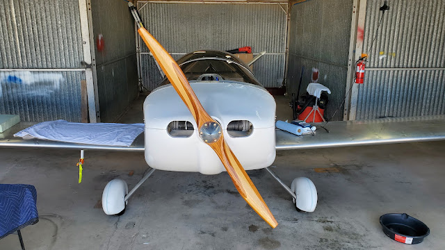
Finally, after just over a year since I ordered it, I have my Prince P-Tip propeller!  I think in the long run I will say it was worth the wait; it looks awesome!


I removed the Sterba loaner prop and the 1/2" spacer I had temporarily installed, and bolted the new prop on.  Here's where it got exciting.  As I mentioned a couple posts ago, with the spacer gone and the prop all the way back at the prop flange face, it is MUCH harder to get the cowl on and off.  I found I was able to round off some edges and do some strategic filing to make the lower cowl possible to install without interfering, however the upper cowl appeared to be totally impossible to install with the prop there.  The aft edge of the upper cowl is supposed to go under the front edge of the windshield skirt, and then you rotate the front down until it meets the front of the lower cowl.  But, until it's all the way in position, the front face of the upper cowl protrudes forward 1/4" or 1/2".  With the prop taking up that space, there's no way to get the cowl on!

I scratched my head over this for a while and finally decided it would be worth it to change how the upper cowl mounts.  For now, I left it perched where it was, just sitting on top but not fastened down.  At least now I can do my weight and balance while I ponder how to fix this issue!

Friday, November 19, 2021

Hours Breakdown #7

I realized I haven't added this all up in over a year so here's where I'm at!

General/Misc: 21
Tail: 72
Wings: 163.5
Control Surfaces: 59.5
Fuselage: 229.5
Controls: 64.5
Landing Gear: 25
Windshield/Canopy: 46.5
Cockpit/Panel: 30
Engine/Firewall Forward: 120.5
Cowl: 32.5
Electrical/Avionics: 121.5

Total: 986 hours

I've got to be getting pretty close to done so I guess the 1000 hours ballpark is looking fairly accurate!

Sunday, October 24, 2021

Cowl Fine Tuning (2)

2 hours

I had already cut a notch into the right side gear leg fairing for this, but after installing the cowl I realized I needed to make a little more room in order to install and remove the lower cowl pin with the gear leg fairings on.


I also filed down some sharp edges and corners that were close to the prop, since I found it tricky to get the cowl on and off without poking the backside of the prop with the cowl.  You can see here where the front of the cowl sits compared to the prop hub.  The temporary spacer I have installed moves the prop forward 1/2" and it's already kind of challenging, so once that spacer is gone I'll have to be even more careful when installing and removing the cowl in order to not scratch up the prop!


RPM Sensor Input Swap (2)

2 hours

I didn't really want to do this, but I need the G3X to record engine time, so I had get my RPM sensor swapped back to the RPM1 input!  The problem was when I switched from the original alternator lead input to the Hall effect sensor, I did a bad job extracting the old D-sub pin and messed up the RPM1 terminal on the J243 connector that plugs into the GEA 24.  That's why I've been just using RPM2.

So, in order to fix this, I had to crawl under the panel and extract all 17 pins I had installed in that connector, and reinstall them into a new connector.  It was nothing too complicated, but the pins are tricky to extract normally, and it was hard to reach everything down under the panel.  Mostly it was just very tedious and uncomfortable, but after much struggling I got all the wires swapped over to the new connector, including the RPM wires now connected back to the RPM1 positions.

Monday, October 11, 2021

Engine Tuning (3)

3 hours

I've done a few engine runs now, just trying to make some adjustments to the AeroInjector, and make sure everything is looking alright.  I have been following the AeroInjector manual, as well as Jeff Schultz's method, explained here:


Anyway, so far I'm using the 2.5 needle and I've adjusted it about 3/4 turn toward lean from the start point, and I think it's in the ballpark.

I also fixed my throttle friction issue from before.  I just bought a rubber fender washer from Home Depot and added it between the throttle lever and the bracket, and now the friction holds it pretty well.

Anyway, as I felt like I was getting the setting close to nearly correct, I tried doing a full throttle run.  I think this is where everything will really start to show up.  Here's what I observed:

(((CAVEAT: I still don't have the correct propeller installed so I will have to re-address all of this later anyway)))

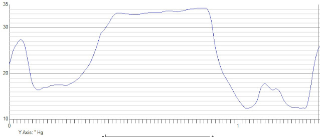
1. I did not get the full 40 in-Hg manifold pressure at full throttle, although the static RPM seemed good.  The Aerovee manual says you should get 3000 RPM static (with the right prop), and the max manifold pressure is 40".  I got about 3150 RPM, which makes sense because the prop is a little too fine.  However I only got up to a max of 34.3" manifold pressure.  I'm not sure if I should expect to get the full 40" static; I will ask Sonex.  I will definitely examine this more once the final prop is installed.

2. EGT's go up fast at full throttle without the plane moving!  I didn't want to spend any more time than I needed to at full throttle because I knew the engine would get hot, but it really does heat up quick.  Looking at the data that the G3X recorded, I spent about 25 seconds at full throttle, and the EGTs quickly rose to about 1200 F, and then gradually climbed to 1300 F.  I did a quick leaning test, pulling the mixture out until the engine stumbled, and in those few seconds the EGTs climbed just to the limit of 1400 F.  That was as far as I wanted to take it anyway, so as soon as the engine stumbled and the EGTs hit the limit I pushed it back to full rich and then pulled the throttle back to idle so everything could cool back down.  The AeroInjector manual says that what you want is an EGT rise of 90-100 from full rich to peak lean at full throttle, so I think I'm pretty close.  Probably close enough to fly with it, but I'll repeat the test again with the correct prop before I call it good!

Here is some data that I recorded.  The graphs, in order, are RPM, manifold pressure, fuel flow, and EGTs.

You can see on the RPM plot where I ran it up to 3150 RPM, and the small dip, rise, and big fall at the end is where it finally was lean enough to stumble, then I pushed it back to rich, and then immediately pulled it back towards idle.

On the manifold pressure chart, you can actually see the boost increase a a little bit as I started leaning, which makes sense as somewhere between full-rich and too lean is probably where the optimal power setting is.

The fuel flow chart shows pretty clearly where I actually started leaning.  At full throttle/full rich it was burning about 7.2 GPH, and then as I gradually leaned it out it made it down to 5.5 GPH which was where the engine finally stumbled.

The EGT chart shows the full throttle/full rich temps around 1200-1300, then a pretty quick rise to 1400 as I did my leaning test.


This data is all pretty useful to have, as I didn't really catch any of this while I actually did it...  I was just trying to not overheat the engine!  The G3X records pretty much everything, once per second, and dumps it into a CSV spreadsheet.  I used the Flight Data Viewer software to view the data, which is a lot easier than just doing it in excel, although that would be possible.  The software is available here:


I did find one more issue during all of this too; the G3X is not recording any engine time!  By now I've ran it for at least a few tenths, but the G3X still says 0.0 hours.  I'm pretty sure I know why.  When I switched from the original RPM input to my Honeywell sensor I tried to extract the RPM pin from the connector on the GEA 24, and I messed up that one socket on the connector.  So I just plugged the new RPM sensor into the RPM2 position.  It works fine, but oddly I think the G3X only counts engine time when the RPM1 value is above the minimum.  I'm pretty sure I will need to replace that connector so I can go back to using RPM1!
Sunday, October 3, 2021

RPM Sensor Do Over (6)

 6 hours

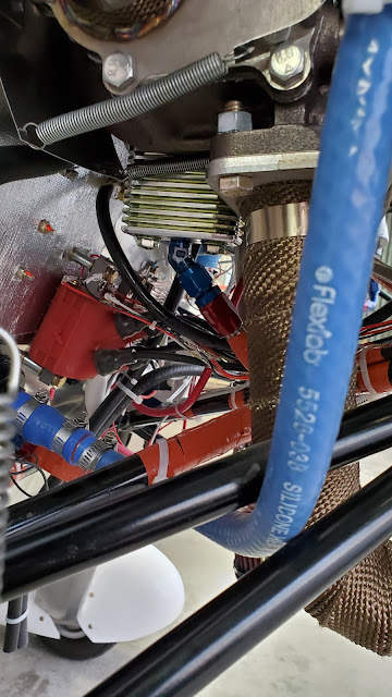
Alright now that the engine is running I can see that my RPM sensor mounted next to the flywheel does not work very well.  My next best idea was to mount it behind the prop hub to sense the back side of the six prop bolts, so I will try that.

This is the area I'm thinking of:


I think I can fit a bracket there without interfering with the cowl.


Here's my first rough draft pattern:


Something like this:


Attempt number 2:


Next I started making it out of some 0.032" scrap.  I started at the bottom and worked my way toward the top, trimming and bending as I went to try and create what I had in mind.  The bottom mounting point is just an unused tapped M6 hole in the front of the engine case, and the top mounting points will be the forward two bolts on the oil breather plate.


This is pretty close to what I was going for, although I made it a bit too close to the bolts so there's not much room for adjustment!


Next I tested my new setup.  I wanted to sanity check the reading on the G3X, so I bought a $10 lawn mower tachometer and attached its sensor wire to one of the spark plug wires.


Then I just ran the wire through the fuel door and set it on the glareshield.


It works!  Here you can see how much more stable the RPM display is than before, and it matches the lawn mower tach as well.


Now that I know it works, I can improve my bracket.  The original was a little flexible, and too close to the prop bolts anyway.  I made a new one with 0.064" sheet, which is turned out nice and solid.  I made it slightly shorter too, so there's more room for adjustment on the sensor itself.  This is still the temporary prop, so I will have to adjust the sensor later I think.


I put the cowl on to make sure nothing interfered, and it's all good.  You can't even really see the bracket from the front so I definitely don't think it'll block any cooling airflow either.