Saturday, December 5, 2020

Engine Oil (1)

 1 hour

This is pretty simple, but I'm going to be out of town for a few months and I wanted to get oil into the engine before that.  I followed the AeroVee manual instructions to add the proper amount of oil, mark the minimum line on the dipstick, then add more and mark the max line.  I used the recommended semi-synthetic oil; they sell it on Amazon for like $90 per 12 quarts.


Finally, I cranked the starter for the first time!!  I removed the upper spark plug from each cylinder, gave everything a good looking over, then gave it a spin.  The engine spun up pretty quick with the spark plugs removed, and I only cranked it for a few seconds at a time until oil pressure started registering (also to adhere to the starter motor's duty cycle limits).

After a couple short bursts the oil seemed to be pumping.  It only took a few cumulative seconds total to see the pressure go up.  Here's a video of one of the first cranks, showing the engine spin up to 250 RPM (assuming my tachometer input is set up correctly on the G3X...), and the oil pressure rises to about 14 psi.


Interestingly, you can also see the "IPS LOW VOLT" advisory message pop up on the PFD as soon as the cranking begins.  I set this up to replace the LED light that came with the intelligent power stabilizer, and apparently it works!  What it indicates is that the IPS is seeing a voltage dip and is doing its job of trying to supply a stable 12v to the avionics in order to keep them running during engine start.  You can see the voltage display on the right side of the screen, that shows Voltage #1 (main bus voltage) drop to like 11.2v, and Voltage #2 (the IPS output) managing to provide more like 11.8v.  So that all appears to work as intended.

Anyway, I let the starter cool down a bit, recharged the battery, and came back a while later for a few more cranks to see how the oil pressure looked.  After three or four total ~10 second cranks, the oil made it to 60+ psi.  That actually seems kind of high to me at only 250 rpm, but the oil is sort of cold (60 degrees F), so maybe it's normal.  I will investigate further later, but I'm guessing it means the oil pump finally was able to fully prime itself and that's why the pressure jumped from 14 to 60.  Here's a video of the last crank I did:


For now, I'm satisfied the engine has some oil in it, and the pump does move the oil around!

Wing Root Electrical/Pitot/Static/AOA Connections (5)

 5 hours

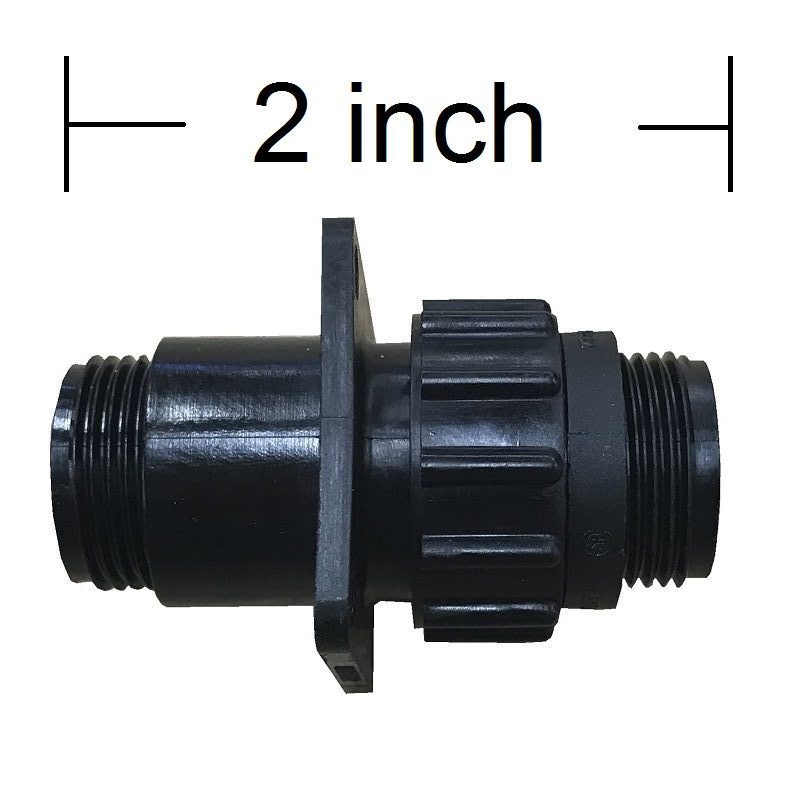
Some of the last electrical stuff left is the wires to each wing for the lights.  There are six wires total that go to each wing.  I wanted some kind of connector that I could attach to the side of the fuselage that would allow me to connect all the wing wiring in a tidy and removable way.  I looked all over for a 6-pin panel mount Molex connector of some kind, but never really found what I was picturing.  Finally I found these AMP CPC connectors at SteinAir.  It's just a plastic cannon plug, and they sell panel mounted 7-pin kits.  Perfect!


Anyway I bought one of those kits for each side, along with the appropriate pins.  I also ordered some panel-mounted quick release connections and 90-degree fittings for the pitot and AOA lines which I will run to the right wing.

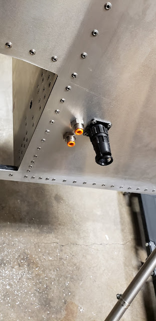
I did some measuring on the wing to figure out where my wires and pneumatic lines should meet the fuselage, relative to the wing spar tunnel.  Then I drilled the holes and mounted the CPC connector and two pneumatic connectors on the right side of the fuselage.  The left side was the same, except just the electrical connector only.


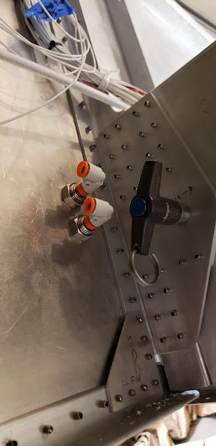
I had to be careful with the pneumatic lines to make sure they wouldn't block the wing attach pin from being installed and removed later.


I also ordered a static port kit from SteinAir while I was at it.  I didn't realize when I ordered it, but the kit came with a pair of ports.  Also, they are tiny!  I decided since I now had two ports I might as well use both, so I mounted each one at symmetrical locations on each side of the fuselage.


Here's the right side port from the inside:


And from the outside.  It's barely larger than a rivet!


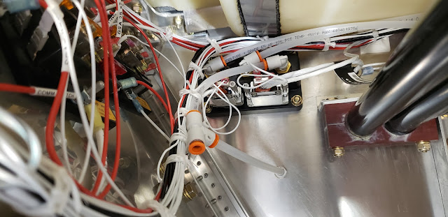
I chose that location because it was out of the way, seemed like it would be exposed to fairly undisturbed airflow, and it made for a short and convenient run to the Garmin GSU 25C ADAHRS that's already on the right side.  The farthest aft port on the GSU is static, and you can see here how I ran a short line to a T-fitting, then connected the right side port, and then I ran another line from the left port to the other side of the T.  I just tied the pneumatic lines to the existing wiring bundle.


Here's one more view of most of the static line:


The other two ports on the GSU are Pitot and AOA.  I ran those lines up and back, following the existing wires again, and then down to the fittings on the side that will go to the wing.


Labeled so I don't mix them up later!


Next came the wires to my cool new CPC connectors.  I used 18awg for the landing lights, with power running from the switch, to a butt connector, and then two wires from the butt connector (one to each CPC).  Same thing with the ground, except starting at the ground block on the firewall.

The wingtip lights got all 22awg wires, one power wire each from the nav/position lights switch and the strobe switch, and then each split into two to feed each side.  One ground wire from the firewall, then split to each side.  Finally, a strobe sync wire, which I just connected from one CPC to the other.


Of course, somehow I ordered like two too few of one of the pins, so it's just about done but I'll have to crimp the last couple pins on later.  Done for now!


Wednesday, December 2, 2020

Fuel/Oil Lines (5)

5 hours

I still had a couple of lines left to do, starting with the fuel supply line.  The plans call for hard lines here, but after reading about the possibility of the lines getting bent and cracking open in an accident, I decided to just use the leftover flexible line I had from the engine instead.  Here's the line from the firewall to the AeroInjector; I later went back and added a fire sleeve over this line.


The line from the shutoff valve to the firewall is pretty much the same:


Next, I installed the Peter Anson check valve in the fuel vent fitting.  It took some finagling, but I got the existing line to connect to a new 90-degree fitting installed on top of this fitting.  It just barely fit under the windshield!!


Finally, I did this oil line from the pump to the engine case.  I originally thought it would be handy to put a bulkhead fitting on the baffle and make two separate lines, but I found that there wasn't enough space to bend the line properly to connect the bulkhead fitting to the fitting on the front of the engine.  This was the best I could do, but I found that the line sticks up too high and hits the cowl!


I re-did it as a single line passing through a grommet in the baffle, and that worked a lot better.  I also put a fire sleeve over the lower part since it's pretty close to the exhaust.

Tuesday, November 24, 2020

Even More Wiring (6)

6 hours

Still more wiring!  Just wrapping up a few more things.  I installed an LED strip along the underside of the glareshield for interior lighting, and wired it to the dimmer switch on the panel.  I had a great assistant for that part!


I found this 12v to 5v converter on amazon and made a simple bracket to attach it to the back of the iPad mount.  That'll provide USB power to the iPad.


I made a fused cable from the battery to this SAE connector; that will connect to the charge port on the side of the cowl for battery charging.


Besides all that, I spent a lot of time tidying up and tying wire bundles together in the interior as well as the engine compartment!!


Sunday, November 22, 2020

Cowl Fiberglass Fixes (5)

 5 hours

The cowl was pretty much installed but I still had some areas to work on.  First, I sanded down and filled in the holes I had drilled through the prop hub area when I initially fit the cowl.  While working in that area I also found a bunch of little voids in the surface of the fiberglass that I also cleaned up and filled in.


Next I installed the side scoops.  I wanted a convenient battery charge port, so I figured a good spot would be in the top of the left scoop.  It's easy to reach but you can't see it unless you're looking for it!  I attached the scoops to the cowl with some epoxy and aluminum rivets.  I added a little bondo to smooth over the edges where it met the cowl too.


Here's the battery charge port in use:


Next was the exhaust exit.  I just did my best to line up a spot on the inside of the cowl that would match the exhaust pipe and drilled a 3" hole with a hole saw.  It lined up close enough!  Then I adjusted the wrap on the pipe so it didn't hang out the bottom of the cowl.


The last thing was a hole for the coolant and oil vent tubes to go through.  I marked a spot where the vents ended up and cut about a 1"x2" opening.  I think with that done, the lower cowl is done!


Saturday, November 21, 2020

Baffle/Cowl Sealing (6)

 6 hours

I had mostly put the baffles together quite a while ago but I never really finished sealing it against the cowl.  Today I fit the rest of the rubber seals!  I found that the gap between the aft fence and the cowl was too large for the supplied seal (mostly because I cut more off of the baffle than I needed to), so I used a 3" rubber strip for that area.  The seal that came with the baffle kit seemed to work well for the front and sides though.