Wednesday, August 5, 2015

RH Stabilator Structure Part 1 (2.5)

2.5 hours

I've got the RH stabilator structure pretty much assembled now, pending updrilling to the final hole sizes and solving one issue that I ran into!

Laying this assembly out was actually easier than I thought it would be.  I figured I should start by constraining the dimensions that are called out on the drawing.  So the first thing I did was attach the forward and aft spars to the tip rib (far right side in the first picture below).  Then I attached the aft end of the inboard rip to the aft spar.


The forward end of the inboard rib attached to the rib clip that's bolted to the forward spar.  This allows you to slide the rib flange and the clip relative to each other in order to properly space the forward and aft spars.  This was tricky with only two hands, but after some serious finagling I got it pretty much perfect so I drilled and cleco'ed that corner together.


With all four sides together, all that's left is to put the four remaining ribs in the middle.


This is where I ran into my issue.  The longest of those four ribs (T11-09) was a little too short, so I had to add a 1/16" shim between the rib flange and the forward spar for it to reach the spar and still be square with the aft spar.  I'm not 100% sure if this is acceptable or not, so I'm going to find out before I actually rivet anything.  But I don't really see why not...


Once I decide what to do about that, though, this assembly will be just about done!  I just need to go back and drill most of the holes to #30, and wait for my dimple die to arrive since some of the joints call for flush rivets.


Stabilator Leading Edge Ribs (0.5)

0.5 hours

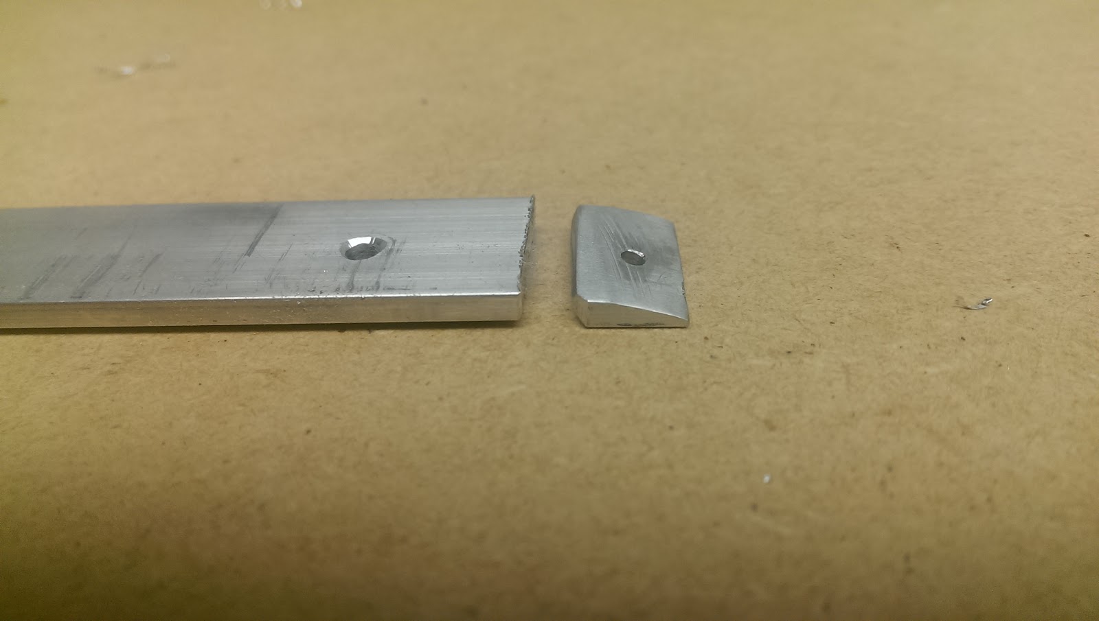
I figured out how to pull those last rivets on my leading edge ribs.  After watching this video, I went and picked up a piece of 1"x1/8" aluminum for a couple dollars at Home Depot.  Then I ground an angle on one end of it, drilled a #40 hole in the face of the "ramp" (perpendicular to the angled face), and cut it off with the bandsaw.  After a few minutes of cleaning up and rounding off the edges with the Scotchbrite wheel, I had my little wedge that would allow me to pull the rivet with my gun at and angle, while still keeping the rivet aligned in the hole.


Then I drilled a #30 hole in the remaining piece of bar stock.  This is just to hold a rivet so I can bend the stem over slightly with my fingers, like this:


Now my little wedge and bent rivet stem fit together like this...


...allowing my rivet gun to pull the stem from an angle that clears the rest of the part.


Done!


Note: I also found an idea for a more elaborate adapter, here.  I might try to make one of these later, but Home Depot didn't have any aluminum that thick and I didn't feel like driving to another store today!

Stabilator Forward Spar Assemblies Part 4 (1.5)

1.5 hours

Picking up where I left off yesterday, went ahead and riveted the RH forward spar assembly together.


Here's the completed part:


After the RH spar was done, I had to repeat the process of cleaning up and deburring the LH side.  once that was done I riveted the LH spar.


Both spar assemblies complete!


The next step will be assembling the stabilator structures.  I realized that some of the joints call for flush rivets, which need dimpled holes, so I went ahead and ordered the Super Simple Dimple Die from Sonex.  After about five minutes of research I decided that would be the cheapest and easiest way to dimple the holes, and I'll need it later anyway for leading edge skins.


Tuesday, August 4, 2015

Stabilator Forward Spar Assemblies Part 3 (2)

2 hours

I picked up a #12 drill bit from the hardware store after work today, so when I got home I started by enlarging the 3/16" holes I drilled yesterday to attach the clips to the forward spar assembly.  It hardly removed any material, but now the bolts now actually fit through the holes... but it's still a tight fit!


With that task done, I took the clips back off, stashed the hardware for now, and attached the leading edge rib (SNX-T04-06) to each forward clip.


I installed two of the four rivets on each one, but the two closer to the angle were not accessible by either my hand riveter or my pneumatic one.  So I'll have to figure out how to pull those rivets later.


For now I just left them like this and put them back on the shelf until later.


Next I took my RH spar cap and channel back apart and set about cleaning up and deburring both parts for the last time.   The channel didn't take long, but the cap took quite a bit of filing, sandpapering, and Scotchbrite wheel-ing.


This doesn't look much different than it did yesterday, but a lot of work was done since then!  This is the RH forward spar assembly ready for rivets.  I ran out of time today, so I will rivet them tomorrow and then start on the LH assembly.

Monday, August 3, 2015

Stabilator Forward Spar Assemblies Part 2 (3.5)

3.5 hours

I got a reply from Sonex this morning, and I'm on the right track after all.  Based on the wording in the Waiex revision log, I thought there would be an updated T10 drawing to depict the new spar cap (T11-03R/L) in the assembly, but the updated spar cap drawing is actually the only new document.  So I'm good to continue, just acknowledging that the forward spar assembly will look slightly different from the drawing since the bend in the spar cap no longer lines up with the clipped corner of the spar channel.  The locating dimensions remain the same, so there's nothing else I need to do differently.


Anyway, back to work!!!

Today I worked on drilling the many holes needed to assemble the forward spars.  After carefully locating the spar cap on top of the channel, I drilled through all the laser cut pilot holes in the spar cap and through the channel, clecoing the holes together as I went along.


I found that my the #40 drill bit gets clogged up with aluminum after a few holes and then the point does not penetrate the channel very well (it updrills the pilot hole easily, but has trouble getting started on the sheet metal below).  I started with my cordless drill, but after clogging up a few bits I gave the drill press a try, and that made it much easier.  I'm going to have to find a way to de-clog my bits though or I'm going to go through a lot of them!


Once the #40 pilot holes were drilled all the way through, it was easy to updrill to #30 with the handheld drill.


Once the RH assembly was all drilled to #30, I repeated everything on the LH side.


The next task was to assemble the two small clips that are bolted to the end of each spar assembly.  These four aluminum angle parts come pre-built as part of the kit.  The T10-6 clips are simple 90° angle, but the T10-5's have been opened up to 100°.  My T10-5L was perfect, but my T-10-5R was off by a few degrees.


It was easy enough to adjust the angle using a clamp and an adjustable wrench, as demonstrated in this video.  Next time I will use a few more layers of tape on my wrench though.  I just covered the jaws with one layer of duct tape, and it still left some small marks on the part.  I'll be able to clean them up with the Scotch Brite wheel later anyway.


Once that angle was fixed, I clamped and drilled the clips to each spar assembly.  My clecos aren't long enough to grab all four layers at once, so once I got the pilot holes drilled I just checked one clip at a time as I updrilled from #40 all the way up to 3/16" holes.  These parts will be attached with AN3 bolts.  The 3/16" holes are a really tight fit, so I might enlarge them later to #12.  But I don't have a #12 bit on hand so I'll deal with that later!

Sunday, August 2, 2015

Starting on Forward Spar Assemblies (0.5)

0.5 hours

Today I decided to take a break from cleaning up the forward spar caps, and started laying out the forward spar assemblies.

At first I was a little disturbed because my spar caps look significantly different from the drawing.  I thought I had seriously misplaced the bend on both of them!  Then I remembered there had been a revision to the WIX-T11 drawing which moved the bend centerline.  After looking up the revised version on the Sonex website (Link), I determined my spar caps were right on after all.

However, the WIX-T10 drawing that I have (rev A) still shows the old spar caps, so it's different from what I have.  I emailed Sonex just to confirm I'm still locating the spar cap and channel correctly, and to find out how I can get the updated (rev B) T10 drawing.  It's Sunday so I don't expect a reply today, but I'm going to wait until I hear from them before I drill any holes in the spar channel.


I also spent a little time organizing and setting up my work area, and it's looking pretty good now!  In a future post I'll show my setup and the tools I've been using.

Saturday, August 1, 2015

Finishing stabilator ribs and spar caps (1.5)

1.5 hours

Today I rebuilt the last stabilator rib (actually the very first one I built) which I had done kind of badly back when I first started. I also managed to straighten out the one rib that got a tiny bit bent while in storage. So now I have all the stabilator ribs done (as long as they all fit and I don't have to redo any).


Next I started cleaning up the spar caps. They come laser cut with pre-drilled pilot holes, but that leaves a lot of serrations on the edges and flashing around the holes. The bending brake also left some marks, so I'm working on buffing them out. I got a good start but there's still a bit more to do.


Once the spar caps are all done I'll be back to where I left off, which is assembling the internal structure of the stabilators!