7 hours
I wanted to use up some more of the parts I've had sitting in boxes for a long time, so I went ahead and tackled the cockpit side panels and installed the brakes and throttles.
My initial thought was I'd mount the brake master cylinder and handle, and then run the lines, set up the calipers, and bleed the brakes so the whole brake system would be done. I got most of that done but then realized that the brake lines go through the cockpit floor, and I don't want to rivet that thing on yet, so there wouldn't be much point in running the brake lines for now.
Anyway, I started with the brake calipers. I had the calipers just slipped over the axles way back when I installed the landing gear and wheels, but I had to pull them off to fit the backing plates. I didn't get a good picture of it, but I used a method I saw on Ryan Roth's blog for using a hose clamp around the gear leg to create a little jacking point. Here's a
link with some pictures. I jacked the plane up like that and worked on one side at a time.
To install the calipers, you sandwich the backing plate between the caliper and the inboard side of the axle, and then a clevis pin goes through the caliper, plate, and a small tab welded on the bottom of the axle. The pin prevents the plate and caliper from rotating around the axle.
I'll start by saying that the holes the plans direct you to cut out of these backing plates don't make much sense. I made the first one according to the plans and it didn't fit at all. All you really need to do to the plate is enlarge one hole for the clevis pin, and create an opening for the hydraulic fitting on the caliper to go through.
I made the first plate per the plans, and once I installed it on the plane it somehow oriented the plate and caliper like 45 degrees off of horizontal, which didn't seem right. I checked the plans page for the wheel pants, and the depiction there had the backing plate pretty much horizontal. I ended up just flipping the plate, and mocked it up with the caliper on the axle with everything approximately horizontal. One of the existing holes on the plate was very close to lining up with the welded tab on the axle as well as one of the four mouting holes on the caliper. That seemed a lot more reasonable. On top of that, the hydraulic fitting that I had cut a large hole for the first time was nearly coincident with the existing large round hole on the plate, so all I had to do there was enlarge that hole a bit, and then everything fit pretty well.
 |
| At the bottom of the plate is the first hole I cut for the caliper fitting, before I flipped the plate and started over. |
 |
| Plate and caliper installed right-side-up. |
 |
| The four nutplates will be used for mounting the wheel pants later. |
When I did the other side, I started by mocking everything up on the axle before cutting anything. This plate ended up being a lot less butchered to achieve the same result!
 |
| Here you can see the welded tab on the axle. The last thing I did on each side was run a 1/4" drill bit through the caliper, plate, and tab to make everything line up. The caliper already had a 1/4" hole, and the plate and tab just had to be drilled out a tiny bit and then everything fit. |
 |
| The hole for the fitting on the right was originally a round hole; I only had to enlarge it slightly to make it fit. |
Next I installed the pistons and brake pads into the caliper. I used a C-clamp to press the pistons in. I put the first one in dry for some reason, which I do not recommend! It was very tight and I don't think I'll ever get it out until I pressurize the brake lines. On the other pistons I lubed the o-rings with a tiny bit of brake fluid and that helped a lot.
Finally, I packed all the wheel bearings with grease and reinstalled the wheels. I still need to drill a hole in each axle for the big cotter pins, but I'll do that later.
Inside the cockpit, I installed the bracket to the forward wing attach angle per the plans. The master cylinder bolts to that bracket, but I don't have the correct hardware yet, so it's just temporarily installed here with Home Depot bolts.
After that, I wanted to install the throttles. However, I knew they bolted to the wing attach angles but I wasn't sure how high to mount them. I realized that the plastic side panels that came with the kit each had a bulge to accommodate each throttle, so I decided to fit the side panels first and then base my throttle locations from there.
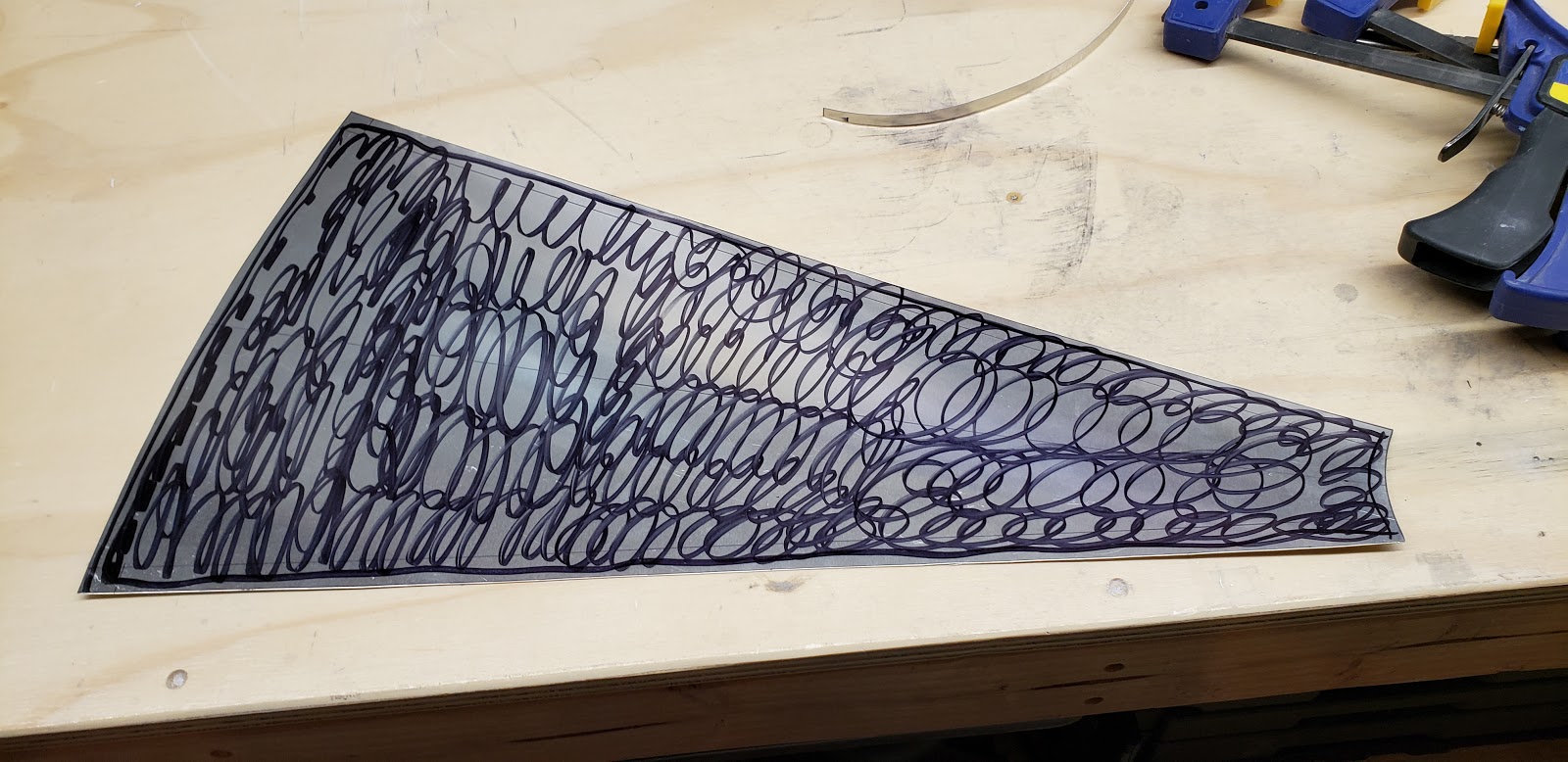
The side panels came in two sheets and needed to be cut out and trimmed to fit. Here's an example of what one of the forward panels started as:
I started with the left rear panel, and just trimmed and test fit over and over until it seemed good. The contour on the bottom matches the seat pan, so I pretty much assumed that area was fixed, and just trimmed the top, front, and back to fit. It took a while but wasn't too difficult. To attach the panel, I drilled the top edge of the panel to the upper longeron. This held the top of the panel in place, and I think the upholstery will retain the back and bottom pretty well.
Once I had the rear panel looking good I continued with the little forward panel. This panel has the bulge that blends around the throttle, so I used that as a reference to place my throttle lever on the wing attach angle.
After many test fits I went ahead and drilled/clecoed the throttle in place.
Here's the let side trimming complete.
Here's the untrimmed right forward panel versus the finished left side for comparison to how it started.
Same thing for the rear panels.
Here are what the two throttles look like. The left throttle accepts two cables. One will go to the carburetor, and the other one drives the right throttle, so they move together. The right throttle only has the one cable attached to it (from the left throttle).
The instructions say to install these cable retainers with a lock nut on each, but I found that the holes were way too close together for the lock nuts to fit. I found I could get them plenty secure without the lock nuts, so I went with that.
Here's the left side throttle plate installed with the panels in place and the canopy closed. Everything fits well! I copied the Sonex factory plane I saw at Oshkosh and drilled an extra hole in the plate to store the canopy locking pin. This has an extra benefit, I realized, in that the pin blocks the throttle lever from going all the way forward. So if I ever forgot to install it, the pin should be right there and it would block the throttle, making it very obvious on takeoff roll that I forgot the pin.
Here's the right side plate. I installed both plates for now without the throttle levers, since I have nothing to connect them to, and they'd just get in the way or get bumped as I work on other stuff. So for now the levers and cables are going back in the box.
A couple more pictures of the completed panels. To attach the top edges, I drilled and tapped the holes I put in the longeron, and used some black coated 6-32 screws.
At the interface where the rear and forward panels overlap, there's nothing behind the panels to screw into. I found these plastic rivets at Lowes that work really nice. The outer part pops through a hole, and then you screw in the inner portion which expands the first part to hold everything snug. I put two on each side and they were good to go!
Here's the part from Lowes. You get two of them for about a dollar.