Wednesday, August 26, 2020

Battery, Garmin Display, ADAHRS, Radio, & GPS Installation (2)

2 hours

I figured there wasn't much need to wait any longer to buy and install an actual battery, so I went ahead and did that.  It just fit right into the box that I had previously installed.  Now I can start testing some of the electrical stuff I've been doing.


Next I installed some of the Garmin components: the GDU 460 display, GSU 25C ADAHRS, GTR 20 radio, and GPS 20A WAAS position receiver.

The GDU 460 fit great in the modified panel!


It's not very deep either.

I stashed the ADAHRS up in the upper forward corner of the right fuselage side skin, above and ahead of the rudder pedal tubes:


I bolted the radio and GPS receiver to the ride side of the baggage compartment, behind the seat.  I plan to put the transponder in about the same place on the left side later.


The remaining things that I have yet to install are the two autopilot servos (mounting already set up but it's on the floor so I'll do them last), the ELT (mounting tray already installed a while ago), transponder (still need to buy one), VHF/GPS/transponder antennas (also still need to order), and the Garmin GMU 11 magnetometer.  The only one I don't really have a plan for yet is the magnetometer.  Garmin specifies a bunch of strict requirements for mounting it certain distances from magnetic items and other electrical components, which I don't think I'll be able to meet on such a small plane.  I will have to do some tests and decide on the best place to put it, but before I can do that I'll need to wire up most of the other stuff.

Sunday, August 23, 2020

Power Distribution & Firewall Forward Wiring (12)

 12 hours

It's finally time to start running wires!  I will post a full electrical diagram and list of components later, because I'm still kind of figuring some of it out as I go.  For now, I'm working on getting all the wires finalized forward of the firewall, as well as any wires that need to penetrate the firewall.

I bought all my wires and terminals from https://bandc.com/ .  They seem to be cheaper than Aircraft Spruce on most of the electrical stuff.  I also bought a few new tools for this project:


Anyway this is hard to show in pictures but so far I've gotten pretty much all the firewall-forward stuff connected, as well as all the switches on the left side of the panel.  That's pretty much everything highlighted on this work-in-progress wiring diagram:


There's still lots to do, including all of the Garmin stuff and the lighting and other assorted things on the main bus!!

Wednesday, August 12, 2020

Fuel Fittings (1.5)

 1.5 hours

With the tank installed again, hopefully for good, I went ahead and installed the fuel level probe and the supply line fittings.

The instructions that came with the fuel level probe didn't have any info about B-model installations, but I quickly realized I'd have to cut the probe shorter for it to fit in the tank (the instructions do describe trimming for a Onex tank).  Anyway I measured the best I could and cut off a few inches.  

The instructions say to use needle nose pliers to flatten the inner brass tube in order to retain the little spacers inside, but I found this to be totally impossible.  Even with much larger pliers I could not flatten the tube enough to stop the spacers from moving!  So hopefully everything stays put, we'll see.  Then I installed the probe.  It was hard to make sure that my trim job was correct and the end of the probe wasn't hitting the top of the tank.  Luckily I have a little inspection camera that I hardly ever use (because it doesn't work very well), so I was able to check that it wasn't touching.

Anyway on to the supply line fittings.  I don't think the instructions were totally clear about what fittings needed to go where, so I sat down and figured it out for myself.  It is kind of convoluted with so many pipe-threaded fittings.

Here are all of those things installed:

The plans call for solid aluminum lines from there to the bulkhead on the firewall, and from the bulkhead to the AeroInjector, but after reading about accidents and fuel leaks, I decided to use flexible lines.  I have some AN6 braided hose left from the oil lines, so I will pick up some appropriate fittings and then use that hose for the fuel supply line.

Monday, August 10, 2020

Panel Extension & Planning (10)

 10 hours

All along I had planned on using a Garmin GDU 450 (7") display for my primary instrument.  However, in the process of trying to lay out the panel, I made the mistake of printing the templates for both the GDU 450 and the GDU 460 (10") display.  I discovered that if I could make the panel just about 1" taller the larger screen would fit!  Once I realized that I couldn't really let go of the idea, so I started figuring out how I could make it work.

I started by just going ahead and ordering the GDU 460 mounting kit.  The kit includes the connectors as well as the little backing plate, which makes a perfect template for the display.  I found a piece of leftover "C" channel way back from the tail kit, and tried clamping that to the bottom of the stock panel.  It took me a little head scratching to visualize how to make the extension work, but gradually I was able to pretty much make it up as I went.  Here's the first mockup:

I ended up making the extension more like 1.25" tall, so that I could fit a row of switches on it.  Here's what I cut out of that piece of channel.  The top side still has the original 90-degree bend, which is cleco'd to the bottom of the panel.


I bend the bottom edge back 90 degrees, just by clamping more scraps to it and hammering it into shape.

The bottom edge doesn't look especially straight in this picture; I made some minor adjustments later!

I bent the little corner tabs in, but I realized I probably cut a little too much material off since it left a gap.  I made a little strip for each corner to tie the bottom and sides together.  I had no idea if this was all going to work or not but the final piece is pretty rigid!

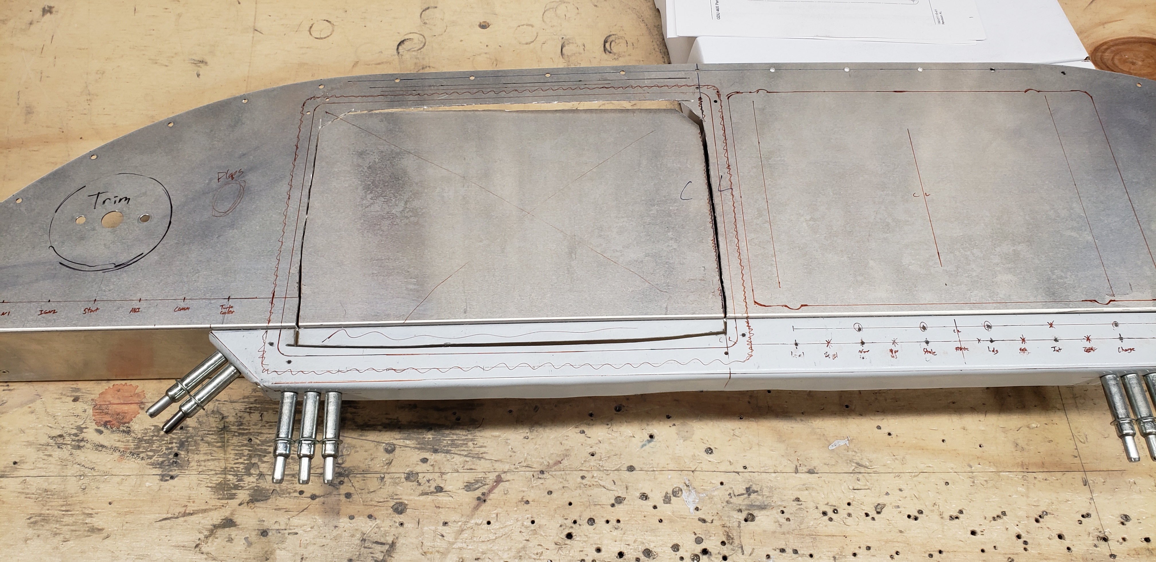
Here's how the extension is attached to the panel.  The large gap between clecos is where the Garmin display will go.

Initial cut for the big screen:


Here's the hole pretty much finalized:


Here's the backing plate attached to the panel.  I also cut out the bottom of the original panel to a little farther than the depth of the display (about 1.75"), plus a little slot on each side so I could install the backing plate across both pieces.


Before I riveted it to the panel I checked how heavy my little creation is.  3 ounces; I think it'll be worth the weight!

The other large item on the panel will be a flush mount for an iPad Mini.  I picked up a Guardian mount and laid out and cut the hole for it next.


Next came switches.  On the left side I mostly copied the factory B-model layout.  The switches I installed, from left to right, are Master Battery/Alternator, Ignition 1 (mags), Ignition 2 (coils), Engine Start, Avionics Bus (all the Garmin stuff), Comm Bus (radio & transponder), and Turbo Cooler.  I spaced each switch 1" apart and placed them as close to the bottom as I thought they'd fit.


Below the iPad I have: Autopilot Level Button (not installed yet in this picture), Nav/Pos Lights, Strobe Lights, Landing Lights, Interior Lights (dimmer switch), and what I'm calling "Charging," which will power the iPad dock, USB charging ports, and a remote ADSB-in if I end up using one of those.  I spaced these switches 1.5" apart, because the dimmer switch is big and it also seemed to fit the space there better.


I still have a few things to install on the left side (flaps switch, alternator circuit breaker, and maybe some indicator lights), and to the right of the iPad (USB ports, copilot PTT button, seat heat switch, maybe the ELT control panel, and the required passenger warning placard), but I don't have any of that stuff yet so that's it for now!

Wednesday, August 5, 2020

Mounting Firewall Stuff (10)

10 hours

This entry covers several little sessions of figuring out where to put everything, getting the correct hardware, and mounting everything to the firewall!

Initially it seemed to me there'd be plenty of room for everything, but it actually filled up pretty quickly.  I had to be careful to lay things out in an efficient way for wiring, and I also had to watch out for things on the forward and aft side interfering with each other (I couldn't put a bolt for something on the aft side through a space where I had already mounted something on the front side).

Here's a list of everything on the firewall.

On the forward side (roughly from aircraft left to right):
Throttle Cable
Mixture Cable
Firewall Penetration (for wires)
Start Button Relay
Battery
Filter Capacitor
Alternator Control Relay
Voltage Regulator
Ammeter Shunt
Master Contactor
2x Ignition Coils
Fuel Bulkhead Fitting
Turbo Cooler Water Pump
Oil Filter

On the aft side:
Cables & Wire Penetration
Fuel Level Probe Transducer Box
Garmin GEA 24 (engine/sensor interface)
Ground Block
TCW IPS-12-4a (power stabilizer)
3x Fuse Blocks

It was fairly tedious to mount all this stuff, mostly because I had to go hunt down all the hardware and wait for it to show up, and also because I couldn't access the front of the firewall to drill holes in a lot of the locations, so I had to drill them from the outside.  Despite that though, I don't regret figuring this all out after the engine is installed, because it made it easy to avoid large engine parts that would have potentially interfered with other parts (like the turbo and exhaust).

It's hard to show everything in photos, but here are a few:


Here are some poorly drawn sketches that might also be handy for reference: